Analog-to-Digital Converter
this peripheral is a very simple one it depends on sampling an analog value and converting this voltage value to a digital code using encoder which converts this signal to a digital code
also according to niquist theorem : Fs>=2Fmax
which states that sampling frequency must be at least twice the frequency of the signal
also if sampling frequency is lower than the signal frequency the aliasing occurs causing the sampling to be corrupted
Quantisation means trying to quantify or make some approximation to the continuous signal to move it to a digital domain in order to read its value
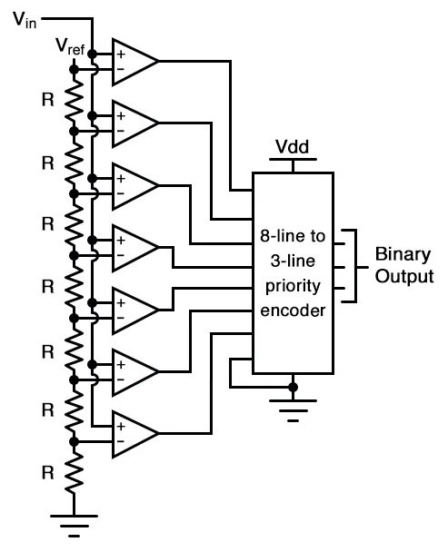
using k-map you can design the priority encoder :D
some characteristics in our stm32
- we have 2 adc peripherals each one has a channel on a specific pins but all the pins are common to the two peripherals the number of pins is about 16 pin those pins are
PA0 -> ADC12_IN0
PA1 -> ADC12_IN1
PA2 -> ADC12_IN2
PA3 -> ADC12_IN3
PA4 -> ADC12_IN4
PA5 -> ADC12_IN5
PA6 -> ADC12_IN6
PA7 -> ADC12_IN7
PB0 -> ADC12_IN8
PB1 -> ADC12_IN9

PC0 -> ADC12_IN10
PC1 -> ADC12_IN11
PC2 -> ADC12_IN12
PC3 -> ADC12_IN13
PC4 -> ADC12_IN14
PC5 -> ADC12_IN15

ADC12_IN16 -> (connected internally to the temperature sensor)
operational functions
- initialization by adc_init functions
-
code for initialization function
char adc_init(char adc, short port, short pin)
{
    //enable clock for gpio peripheral for i/o mode selection
    //configure pin as input
    //configure the pin as input analog function
    init_GP(port,pin,IN,I_AN);

    volatile int portsChannels[] = {pin,8+pin,10+pin};
    volatile int ADC_RCC_APB2ENR[] = {0x201,0x401};

    //enable clock for ADC module
    RCC->APB2ENR |= ADC_RCC_APB2ENR[adc-1];
    //reset control register for adc12 module
    ADC1->CR2 = 0;
    //select the channel to be used
    //we can use 6 channels at the same time but read on
    ADC1->SQR3 = portsChannels[port-1];
    //make ADC on then wait Tstab time to which is two clocks of clock adc connected to
    ADC1->CR2 |= 1;

    __asm__("nop \n"
            "nop \n");
    ADC1->CR2 |= 1;//must be on two separate write commands

    ADC1->CR2 |= 2;//set bit 1 to configure ADC for continuous conversion

    return 1;//return 1 indicating successfull initialization
}
-
- checking by adc_check function
-
Reading the flag that says the data is ready
    char adc_check(char adc, short port, short pin)
    {
        volatile int ADC_SRs[]={(ADC1->SR & 2), (ADC2->SR & 2)};

        return ADC_SRs[adc-1];//read EOC bit which is set to 0 when Conversion is not complete  and set to 1 when Conversion completed
    }
-
- receiving by adc_rx function
-
Reading the ADC value
    int adc_rx(char adc, short port, short pin)
    {
        volatile int ADC_Data_Register[]={(ADC1->DR), (ADC2->DR)};
        return ADC_Data_Register[adc-1];//read data register of 0xfff maximum value from 0 to 2^12=4096
    }
-
operation with interrupts
we can use interrupts but we need to define a flag for that operation to indicate the peripheral fired the interrupt by setting the flag of the module firing an interrupt
following these steps to define an interrupt with watchdog interrupt firing events for low and high thresholds interrupt events
- first we need to define the flags of each event and module to check because of all events mapped to the same function location of ADC1_2_IRQHandler
    //which adc we will use ? adc1
    int adc1_int = 0;
    int adc2_int = 0;
    //data container argument
    int analog_rx = 0;
    //flag indicating data interrupt occured and analog_rx is loaded with data
    char adc1_flag = 0;
    char adc2_flag = 0;

    int adc1_wd = 1;
    int adc2_wd = 0;
-
initialization of interrupts with watchdog interrupts firing events
adc_init(adc1,PA,0); //enable interrupts for ADC //ADC1->CR1 |= 0x20;//setting up the normal interrupt ADC1->CR1 |= 0x800000;//enable Watchdog bit AWDEN ADC1->HTR = 0xC00;//set High threshold ADC1->LTR = 0x500;//set low threshold ADC1->CR1 |= 0x40;//enable end of conversion interrupt __disable_irq(); //we have one interrup for the two adc peripherals and we have three interrupt modes we use EOC from them NVIC_EnableIRQ(ADC1_2_IRQn);//enable nvic interrupts for this peripheral __enable_irq(); -
also we need to define the asyncronous function of an ADC interrupt
      void ADC1_2_IRQHandler(){
          if(adc1_int){
              //set bit EOCIE to 0 //then enable it after reading data
              ADC1->CR1 &= ~0x20;//disable interrupts for adc to prevent other adc from firing an interrupt
              analog_rx = ADC1->DR;
              adc1_flag = 1;
          }
          if(adc2_int){
              ADC2->CR1 &= ~0x20;
              analog_rx = ADC2->DR;
              adc2_flag = 1;
          }
          if(adc1_wd){
              //this interrupt will occur outsize the range of HTR, LTR
              //set bit EOCIE to 0 //then enable it after reading data
              ADC1->CR1 &= ~0x40;//disable interrupts for adc to prevent other adc from firing an interrupt
              ADC1->SR &= ~0x01;//to prevent looping we need to lower that bit
              analog_rx = ADC1->DR;
              adc1_flag = 1;
          }
          if(adc2_wd){
              //set bit EOCIE to 0 //then enable it after reading data
              ADC2->CR1 &= ~0x40;//disable interrupts for adc to prevent other adc from firing an interrupt
              ADC2->SR &= ~0x01;//to prevent looping we need to lower that bit
              analog_rx = ADC2->DR;
              adc2_flag = 1;
          }
      }
operation with multi-channel
challenges :
-
the is 2~3 ADCs in stm32f1 family
-
only 1 channel can be read at the time
generally we have two ways to solve this problem
the only way is reading channel by channel with two ways
-
scan mode -> scanning the 17th channels using the sequence register ADC_SQRx(x = 1..3)
-
Discontinuous mode -> scanning limited number of channels using the seq register ADC_SQRx (x=1..3)
both of them are using DMA peripheral to make the manupulation but for now we are not gona use this configuration
- setup the ADC_multi_channel_init we can read the comments to understand the code step by step
    void ADC_multi_channel_init(int adc,int channels, int * adc_channels){
        int i=0;

        for(i=0;i< channels;i++){
            if(adc_channels[i] < 8){
                init_GP(PA, adc_channels[i], IN, I_AN);
            }
            else if(adc_channels[i] < 10){
                init_GP(PB, adc_channels[i]-8, IN, I_AN);
            }
            else if(adc_channels[i] < 16){
                init_GP(PC, adc_channels[i]-10, IN, I_AN);
            }
        }

        volatile int ADC_RCC_APB2ENR[] = {0x201,0x401};

        ADC_TypeDef * ADCs[] = {ADC1,ADC2};
        //setup the clock for the ADC peripheral
        RCC->APB2ENR |= ADC_RCC_APB2ENR[adc-1];

        ADCs[adc-1]->CR2 = 0;//ADC off and reset all bits
        ADCs[adc-1]->CR2 |= 1;//ADC on
        __asm__("nop \n"
                "nop \n");
        ADCs[adc-1]->SQR3 = adc_channels[i];

        ADCs[adc-1]->CR2 |= 2;//continuous reading
        ADCs[adc-1]->CR2 |= 1;//starting the conversion
    }
- then we need to initialize the reading function whcih will read the values and saves them to the buffer by reference but it will read them iteratively each time this function is been called, let’s look at this function
    void ADC_Multi_channel_rx(int adc, int channels, int *adc_channels, int *analog_rx){
        ADC_TypeDef * ADCs[] = {ADC1,ADC2};
        int temp_rx = 0;
        int i = 0;

        while(1){
            if(adc_check(adc)){
                temp_rx = ADCs[adc-1]->DR;
                analog_rx[i] = (temp_rx);
                i++;
                if(i == channels){
                    i =0;
                    ADCs[adc-1]->SQR3 = adc_channels[i];
                    break;
                }
                else
                    ADCs[adc-1]->SQR3 = adc_channels[i];
            }
        }
    }