Timers
timers are counters connected to a certain clock and can trigger an interrupt and can be configured to work as PWM or input capture to measure a signal frequency
types of counters
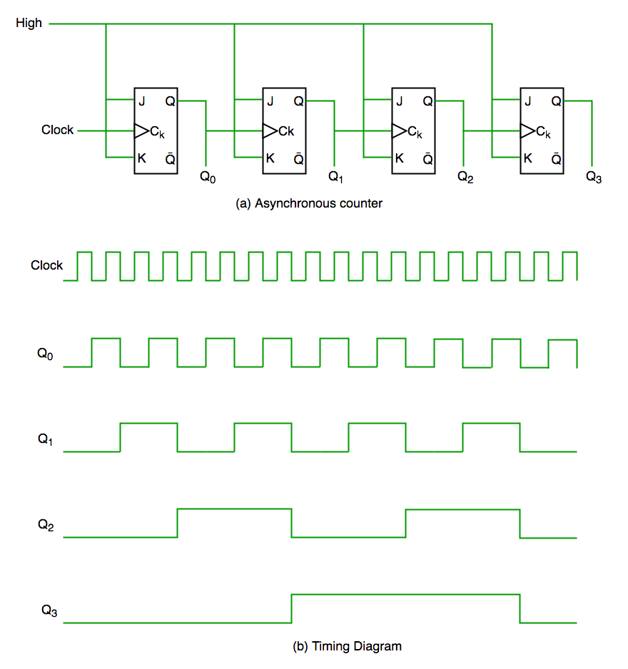
- Asynchronous Counter
is a counter consisting of many JK-flip-flop connected together with different clock source as follows
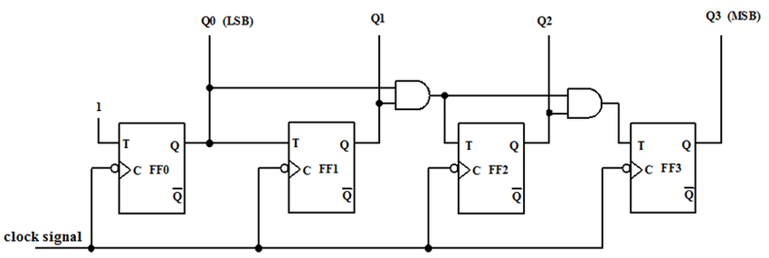
- Synchronous Counter
is a series of registers connected with the same clock source
for our stm kit it have three types of Timers
- Basic Timers
- General Purpose Timers
- Advanced Timers
each type has different features according to our usage and application but for now the main features we gona need is delay, timers interrupts, PWM and Input capture
- Timer Operation
- first we need to enable clock for the selected timer
- second we need to define the clock divider through PSC regiseter
-
third we need to define clock counter ARR register to divide the clock cycle to reset after this register Value so for a delay function we can continuously check the CNT value reaches a certain value also we need to start the counter and define the counting mode with CR1 register
RCC->APB1ENR |= (1<<2);//enable clock for timer 4 peripheral

TIM4->PSC = 8; //define clock divider
TIM4->ARR = 1000;//define Auto reload register value when CNT reaches this value it will reset to 0 and start over according to counting mode
TIM4->CR1 |= bit(0) | bit(2);//enable counter and define counting mode
while( TIM4->CNT != 1000 );
Some Notes
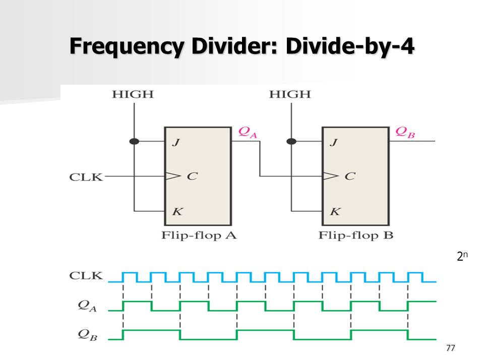
Clock Divider Circuit Diagram
it is used on register PSC to divide input clock to timer peripheral
Clock Multiplier
it is used on RCC to increase the clock
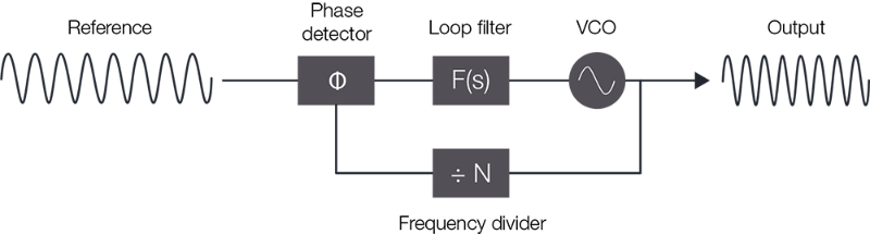 this circuit consists of
-
phase-locked loop
which takes two digital signals and determines the phase difference between them in order to reduce the error in phase of generated signal - low pass filter
this circuit is noting more a resistor and a capacitor to block phase detector AC or high frequency part - VCO Voltage controlled Osillator
this circuit has many configurations such as ordinary OSCILLATOR circuit and RCL circuit at resonance level and 555 circuit can ne used too, this block is responsible for generating a frequency at a certain voltage level
this frequency generated through VCO is divided by n (multiplied frequency value) and passed to phase detector to identify the error in phase between the input and output signal then try to correct the phase by generating apropriate voltage level to generate apropriate frequency with VCO